Thursday, January 26, 2012

Trying to Finish - Part 2

A couple of other little steps finished today pushing me closer to completion:

  • Reassembled the front indicators and tested the indicator wiring.
  • Used front indicators to confirm Hazard relay works OK.
  • Rerouted water line connections for bleed line and EGR valve, and connected up new water lines from these back to expansion tank.
  • Configured main water lines from thermostat back to the expansion tank 
  • Machined up mounts for reversing lights.
I now need to wire in the side repeater indicators, so I can fit the scuttle, which will allow me to mount all the tanks and reservoirs, the windscreen and the wipers.

Once I fit the last R pin to the front uprights, I will also put the front mudguards in and then the nose cone.

Interior - Part 3

The carbon fibre centre panel is a tricky piece to fit. It holds an auxiliary power port and the wiper washer button. It would normally hold the heater controls, but I have chosen not to fit a heater. I have also chosen to use this panel to mount the original Focus cluster on, which I will explain later in this post. First task was to enlarge the holes to hold the switches and ports. This was done with a stepper bit and a sanding wheel in the Dremel. 


With that done, I turned to the mounting bracket for the original Focus. This is an idea borrowed from a fellow Birkin builder Maurice. The mount is a right angle aluminum bracket, bolted to the top of the carbon fibre panel. From here, two stainless steel bolts go through the front of the bracket, and secure the Focus cluster through the bottom.
An aluminum bracket is passed through the top of the Focus cluster, and it runs down the front and back of the cluster, and is clipped under the bottom. Then a wide piece of aluminum is fitted over the back of this bracket and secured to the bolts from the front. This makes the mount very solid and the cluster is held tightly in place. The circle on the left at the back is the warning chime speaker, which has been "modified" to lower the volume of the warning chimes. Because the front of the cluster has all the original LED warning lights, I have covered this with rubber, which is secured by the middle aluminum bracket and the two cable ties. The rubber sheeting also acts as a damper against vibration. The LEDs need to be covered otherwise I will get unwanted light from under the dash, and it will also bleed through gaps in the dash switches at night.


With the Focus cluster mounted, the next step was to mount the carbon fibre panel in the car with the cluster on top. Here is where I have stolen another idea from another fellow Birkin builder Andrew. I riveted two 90 degree brackets on the frame, and put rivnuts in those to receive screws through the carbon fibre panel. I used a trick Andrew posted on his build diary to line these two up so I could drill the holes through the carbon fibre. This worked a treat and very soon I had the panel secure in place, and the Focus cluster wired. This step has taken a long while to do and has been fairly fiddly, but I am pretty happy with the result. Its tidy and looks professional, not that you can see it from the cockpit!


Final position from above. I will probably reroute the cables back into the tunnel and bring them up through the carbon fibre panel into the cluster.


This what it looks like from the cockpit and behind. I will paint the bolt heads black.


This is what it looks like from the passenger foot well, before the scuttle goes on.

Interior - Part 2

After I loosened it (someone used Loctite initially!), Steve was able to remove the gear knob so that gear shift shroud could be fitted onto the tunnel. The gear knob was refitted, sans Loctite :) This now just leaves the carbon fibre centre panel to fit over the gap above the tunnel. You can see where the tunnel is bowed a little downwards, so I have riveted in a black strip of 3mm aluminum to hold the front of the tunnel straight.


I was also able to fit the interior side panels which need to go in before the scuttle is fitted, as the scuttle has right angle brackets under the dash that secure it and hold the side panels in simultaneously.

Wednesday, January 18, 2012

Interior - Part 1

As I am starting to wrap up, I am able to finish a few things off. In order to get the scuttle on, I need the Focus cluster mounted, which needs the carbon fibre panel mounted, which needs the transmission tunnel mounted!

Since I got all the transmission tunnel carpets in over the weekend, Monday night I was able to fit the transmission tunnel, and the handbrake boot....gear lever shroud will need to wait as I can't get the shift lever knob to budge ;)

The transmission tunnel was surprisingly easy....and I was ably assisted by my oldest son (who was going to help me build the car......).

With the tunnel in, I was also able to fit the rear bulkhead lining, but only using the top mounts. I have yet to drill and secure the panel at the bottom. This only leaves the seat belts to go back in, the seats, the main carpets and the carbon fibre centre panel to finish off the interior. 

Sunday, January 15, 2012

Trying to Finish - Part 1

Happy New Year! I thought I had better update the diary as there has been some progress since the drive, although I have been limited to night time building and wet weekends only as a new pool and Christmas were priorities.


I have managed to prioritize my To Do list and I now know what needs to be done and in what order to get to engineering and rego. Also as an early Christmas present the NSW RTA was merged with the Maritime agency, to create the Roads and Maritime Service (RMS) dept. They subsequently released a new certification scheme called the VSCCS the week before Christmas. This makes it somewhat more predictable to engineer and register an ICV now in NSW. This is not a short cut, as you still need to build a quality car to the current ADRs, but it makes the certification process more consistent. All good!


So what has been done since I drove it back in early December? Lots of deconstruction in order to finish things off. A quick summary of tasks completed, then some photos:

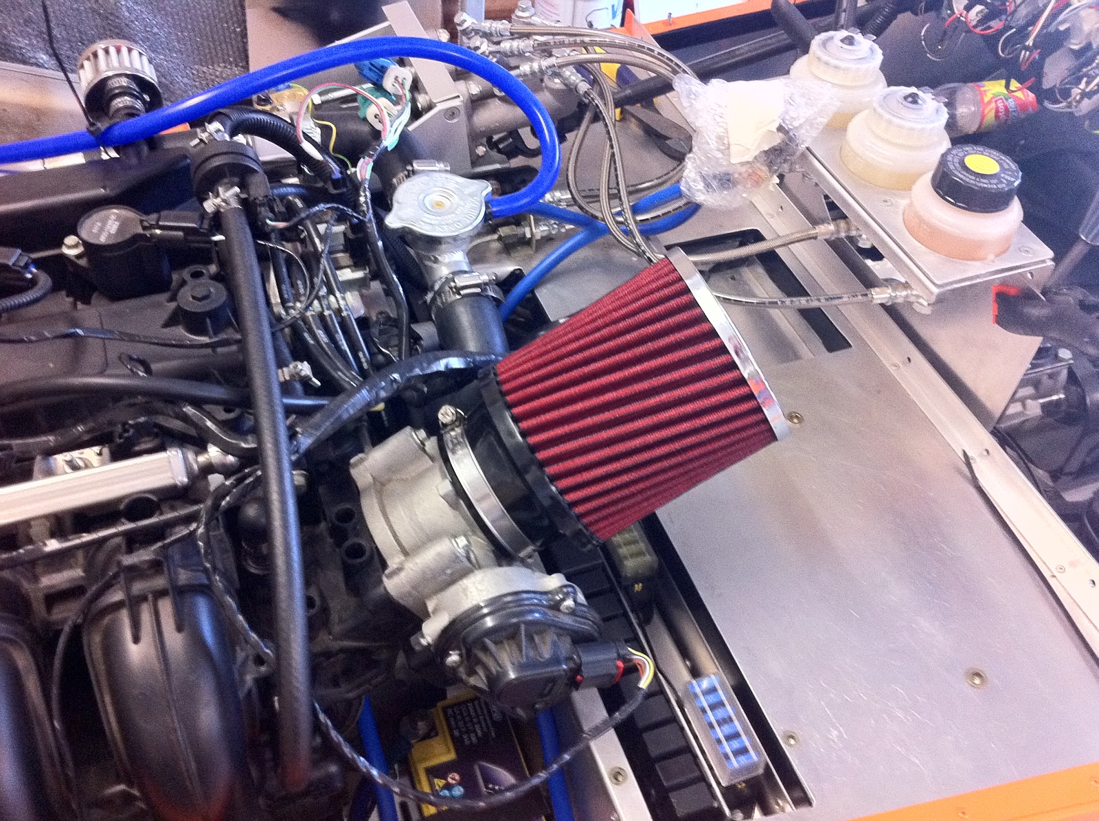
  • Completely rerouted the engine looms and ECU loom to hide the wiring, and rerouted the fuel lines and evaporative lines. This has made the engine very tidy (photo below). Many thanks to Steve for his help with this.
  • Modified the throttle mount angle and notched the pedal box frame for the drive by wire connector. The drive also proved the that I had moved the pedal box to far forward, so its now back where it started. Pedals are all now finished. Once the cable is secure the pedal box cover will go on.
  • Removed the cooling expansion tank, and rerouted all the cooling lines to face backwards in preparation for the mounting of the expansion tank on the scuttle.
  • Fitted all the interior carpets.
  • Had the seatbelt lower mounting plates modified to be compliant with ADRs.
  • Successfully tested all of the dash switches and wiring (so the scuttle can go on)
  • Fitted all of the wiring penetrations with grommets, and checked all the wiring cable ties.
  • R pinned all the front ball joints.
  • Tested the reversing switch and lights.
I have also purchased all the lights and started preparing them for mounting, either by fabricating mounts, wiring up adapters or painting brackets.

A couple of photos of the progress.
Engine wiring tidied up and fuel lines rerouted.


Seat belt mounting plate that had to be replaced with a 90 degree pivot mount that has the forces in a direct line with the bracket. Hemco are replacing these this week.


This is the headlight mounts before the first modification.
This is the headlight mounts after the holes were machined larger to take the light stalks. I still need to machine down the height of the adapter so I can get some thread to bite underneath.


These are the front indicators and mounting stalks as I received them, all chromed up.


This is what they look like after 3 coats of satin black! I have decided no chrome on this car, so every chrome part is being either painted or etch primed and painted satin black.


This is the rear license plate light (painted black), fitted, wired and working. I suspect the fuel filler may have to be painted black as well :)

Saturday, December 10, 2011

First Drive (sort of)

After getting the throttle in last Sunday, I arrived home from work on Monday (in the rain) and my kids said "Why don't you see if it drives Dad?". Hard to argue with that logic so I donned the Puma Drift Cats (the only shoes for driving a Clubman) and headed out to the garage. After warming her up for a few minutes, we set out on an exploratory trip up the driveway (cameos and stupid commentary courtesy of kids shooting the video).


First drive video

So not very exciting, but it proved a few things. Firstly, the clutch master cylinder positioning is good, and the clutch take up and release points aren't bad, and there is no drag (this means the engine and gearbox stay in). Secondly, the brakes work, just need to release the pivot bearing a little to the get full pedal return. Lastly, because it was nearly dark when I tested it, I was able to test all the dash lighting and switches, and they all work as well. So all in all, a good if not massively exciting test run.


On the second run I gave the throttle a little stab, and was shocked at how hard it wanted to take off.....cannot wait to get it out and running properly!!!!


The car is now back up on chassis stands and I am ripping bits off it in order to get things finalised. Not long now!!!

Monday, December 5, 2011

Throttle Mount

As the Duratec uses a drive by wire throttle linked to the ECU, I needed to mount the throttle pedal body somewhere near the existing pedal box. After seeing what other builders had done, I elected to suspend the throttle pedal body on aluminum plate off the back of the pedal box. This took 2.5 attempts to get a mount I was happy with, as the angle and left/right position of the bracket, and the pedal on the bracket is crucial. To far right and the throttle connector fouls the pedal box and frame. To far left and the brake will hit the throttle (ok for heel and toe I guess!).


I also fabricated up from 3mm angle a pedal cover for the throttle which is bolted through the old plastic throttle lever. All of these pieces are bolted up temporarily until I am happy with the position. In sitting in the car I now find the pedal reach is to far, which is ok as I moved the pedal box one adjustment forward....so I guess I am now moving it back one adjustment.


So with the throttle mounted.....I may be able to drive it now?!?!?!?!?!?

Wednesday, November 30, 2011

Since the start....

I figured once I had the car started......another few nights in the garage would see it finished! Another wise Birkin owner (lets call him Maurice!) told me I would be surprised how long these simple finishing tasks would take to complete.........

One of the things I did leading up to the start was have a To Do list that had all the preceding tasks prioritised. Post engine start, I had prepared a list of tasks to finish the car (about 80 tasks), but had not done any prioritising. So many a night has been spent in the garage about to start a task, followed by 60 minutes of pondering (Steve call's it procrastinating ;) the preceding tasks and then walking back into the house having done nothing. For example:

  • To mount the reservoirs and expansion tank on the scuttle
  • Needs the scuttle to be mounted
  • Which means all the wiring has to be finished and checked
  • Which means all the lights have to be fitted and tested
  • Which means the mudguards need to be fitted
  • Which means I need to move the exhaust and finalise the wheel alignments
As a result not a lot of progress. I have managed a few small jobs and these are leading to the chance for me to at least drive the car up the driveway for the first time.


I have modified the pedal box to remove the existing cable activated throttle in order to mount the Focus drive by wire throttle. This involved cutting two parts of the original pedal box off that held the throttle pivot and removing some spacers. Those who have this pedal box will recognise where I have cut it and how neat I have been! This also meant switching the brake pedal pad to the left side of the lever to accommodate the larger throttle. I have since fabricated throttle mount prototype 1 which didn't fit well, and am now half way through prototype 2 which should be the winner. This will allow the throttle pedal to be mounted and a potential drive up the driveway.

I have also removed the Fuel Pressure Regulator and reconnected all the fuel lines and run the engine in that configuration.

 As part of the finishing the wiring, I needed to connect the reverse lights to the reverse switch in the Type 9 gearbox. This is what the switch looked like - missing the connector pins!. So I have purchased a new one and fitted it to the gearbox and completed the reversing wiring. 


On top of all that I have been testing wiring into the dash, and have pulled the main loom off the engine and put rubber grommets into all the body holes, cable tied up the wiring to be in spec, and wrapped all of the engine loom wiring in plastic shielding to protect it in the engine bay. 


I have all the lights arriving this week and will make a concerted effort to get the finger out and get more done.

Monday, October 3, 2011

Engine Start Attempt

As it was a long weekend here, I had been planning for a few weeks to try to get the first start attempt organised for this weekend. After finishing the last few things on my To Do list we ran some electrical checks, then dropped her back on to her wheels. From here we pulled all the spark plugs out to lower compression and then cranked the engine over by hand to circulate some oil. We then cranked the engine over with out any fuel, to make sure it cranked. It did! This means most of the electrical system so far is working with no blue smoke coming out.


We then rolled her out the front, and broke out the fire extinguishers. I put 5 litres of fuel in the tank, and we got ready to fire it up. Turning the key got it to crank, but that was it. A glance at the fuel pressure gauge indicated no pressure. So either we had the filter in the wrong way up, the the FPR incorrectly set up, or the pump lines were wrong. We pulled the line off between the pump and the filter, and cranked it again back into the jerry can. Still no fuel?!? The pump was cutting out fairly quickly, so we surmised maybe there was not enough fuel in the tank, so we added 5 more litres and tried it again. Fuel started to splutter out of the hose! We reconnected it back to the filter and clamped it, then tried it again. No start, but this time the FPR went up to 90psi.....which is double what we need. I adjusted the FPR back down to 42psi and locked it off.


Put the key back in and cranked it over......


:)   Very happy!


It starts easily, runs very smoothly and revs nicely. Its fairly quiet with the muffler I have fitted. I need to reorganise the cooling, but it pressurised OK and nothing leaked. Best of all the fuel system worked perfectly (once we had enough fuel in it). Its hard to believe I have managed to pull together a bunch of parts from all over the world and combine them into a single working unit.


This is a major milestone as I can now engage the engineer to start certifying it for rego, and I can also start putting the finishing touches on it such as the windscreen, roll bar and the lights. 


Many thanks again to Steve who assisted with the troubleshooting and shared in the elation of the first start (although no feet in the video as he was shooting it on the phone!)


Electrical System Check

All work this week has led to a potential engine start. Today all that work was completed, so we made the final battery connection (body earth is good because I got the spanner to arc from the positive to the body) and switched on the master switch. This put put power on the old Focus dash cluster, and allowed us to switch the car to ON and see what worked. Expecting to hear potentially nothing, we heard the lovely sound of the fuel pump pressurising and the throttle body position sensor motor humming.


The old dash cluster lit up revealing the original engine mileage.....12,791km. On the downside, there are few errors we need to remove, and these have interesting alarm chimes sounding. Putting the old key near the PATS reader, we were able to make it crank over.........

Pod Air Filter

I didn't get the factory air box and air filter from the donor Focus, so I have fitted a pod filter in the interim to let me start it and get it engineered. Depending on the induction noise I may use it for rego........Looks cool though :)

Fan belt

Fitting the fan belt means I have the alternator 100% fitted, and the idler pulley refitted. The belt is a 5PK1260, which I cut one rib off using a Stanley knife. Being 4 ribs only means I can move it backward or forward for adjustment as the crank pulley and idler pulley are both 6 ribs.

Saturday, October 1, 2011

Alternator - Part 2

After trying to fit the alternator I had, I decided it was to big for the space it was supposed to fit. I contacted the wrecker I got it from (New Model Wreckers) and they happily agreed to swap it for whatever I wanted. I went out there and 10 minutes later I had a tiny little Denso alternator from a Diahatsu Cuore. This is half the weight of the previous one and it fits into the right space without having to remove anything. Only problem now is that Eurospeed didn't have any billet mounting brackets in stock, and had no production runs planned for over 2 months. 


If I want to get the car started soon, I would need to fabricate the brackets myself, using 6mm aluminum plate. In the words of Jeremy Clarkson...."How hard can it be?".


This is prototype 1. The new alternator is mounted with the terminals outboard, and with the 10mm straight through bracket at the top. Prototype 1 was designed to bolt up onto the block about halfway up the block. The issue with this attempt was I cracked the 6mm aluminum while bending it, and it was fractionally forward of where it needed to be,
Here is prototype 1 mounted on the block.

Here is the alternator mounted on prototype 1. The issue here was the top mount appeared to be to low. This meant the bottom of the alternator was wedged between the frame and the block. Worse still, the bottom mount on the alternator fouled the bottom mount point on the block. 

Here is prototype 2. This was similar to 1, however I heated the aluminum while I bent it to avoid cracking. The alternator was reversed so the top pivot now was an 8mm threaded hole. The new bracket was drilled so that the pivot point was higher. Problem here was the main terminals now contacted the block, and the alternator body still fouled the frame, with little or no adjustment. Overall the alternator appeared to low.
Here is prototype 3 on the alternator, next to the remnants of prototypes 1 and 2. This new approach came about after a few beers and sitting looking at the problem for about an hour. I decided to see if I could use the original alternator mount as a hanger, rather than bolting the bracket to the block down lower. I put a bolt in this mount and hung the alternator on a cable tie to test. Looked OK. 


Prototype 3 was fabricated using 40mm right angle that is 6mm thick, shaped to suit the mount and the alternator. This is revision A with the alternator mounted. The issue here was that the bracket fouled the alternator bracket and didn't allow any adjustment. The alternator is spaced backwards with one washer.

This is revision B of prototype 3. I cut away the bottom half of the mounting face, and this allowed a larger range of adjustment. Prototype 3 mounts the alternator much higher, and allows lots of space either side of the alternator. This version means the alternator doesn't foul the block or the frame. Underneath here all of the alternator wiring is complete and the bottom mount is a 90 degree tab to locate the bottom mount onto the block. Prototype 3 is the winner! Tomorrow I can fit the fan belt and the idler pulley.


Sunday, September 25, 2011

Fuel Pressure Gauge

The Duratec engine has a returnless fuel rail. Because I am not using a Focus fuel pump which has a built in regulator, I had to add the SARD Fuel Pressure Regulator. In order to set the pressure correctly on the system to around 40-42psi, I had to add a temporary fuel pressure gauge on the line to the rail. I have obtained a Speco Meter 100psi mechanical gauge on ebay and an 8mm line adapter. This will be removed once I have the fuel pump running correctly and the engine starts OK.


Exhaust System - Part 1

This is Part 1 because in order to pass rego here, you need to meet stringent emissions levels and various noise tests. So to get past rego I have had the first exhaust fitted which is functional only (not pretty!). It consists of a Commodore VZ catalytic converter, and a very large, heavily baffled muffler, which then continues under the car to a rear exit. It is shielded for rego as well.