My wife said I needed a hobby.....so imagine my surprise when I showed her a picture of a kit car, and said "Let me build this.."......and she said "I think that's a great idea!" So this blog is a chronicle of my efforts to piece together a Birkin S3 Clubman, and a tribute to my wife's patience and understanding.
Wednesday, August 31, 2011
Cooling System - Part 2
Alternator
I sourced a second hand alternator using Parts Locator. Its from a 2005 Diahatsu Sirion (1.3litre). Its larger than expected but will fit the space available. I could have also got one from a Mira or Charade. Most important is the serpentine (ribbed) pulley which matches my belts. Just needs a plug connector which Geoff Mills is adding now. I now need to fabricate two brackets to mount it to the block.
Tuesday, August 16, 2011
To do list - Engine Start
I thought I should post a quick list of things I believe I need to finish to allow me to get to the first engine start:
ALL DONE! Actually it took another 6 weeks!
Things I missed that I had to also do:
Complete brake bleedFit final cooling pipes and hoses to expansion tank.Fit throttle pedalFit and wire alternatorFit engine wiring and connect in ECU and dash loomBuild and fit final wiring harness between body loom and engine loomFit exhaust and catalytic converterFill and test water and fuel systemsFit belt to pulleys
ALL DONE! Actually it took another 6 weeks!
Things I missed that I had to also do:
- Wire up the water temp and oil pressure senders
- Fit an air cleaner
- Refit the ignition vacuum line
- Wire up the fuel pump
Oil Pressure Sender
Fuel System - Part 5
As mentioned in a previous post about adapters, I have found an adapter to connect a fuel line to the service port on the SARD fuel pressure regulator. Ideally this would have been a hose tail with a tapered thread, but given the port was 1/8PT (JIS), I either needed to find an 8mm hose tail in this thread fitting or a 1/8 BSP. Next best thing was an adapter which came from Speco so I could use the SARD supplied hose tail. So the reg has a line in on the left, line to the fuel rail on the front, and a line to the return on the bottom. I will need to fit a pressure gauge in line on the hose to the fuel rail before I start it to ensure I have a max pressure of about 42 psi. I have fitted this to the bulkhead behind the passenger seat next to the fuel filter, and have finalised all of the hose connections. Fuel system - FINISHED!!
Adapters
In order to fit the VDO senders for oil pressure and water temp, plus finish of the fuel regulator I needed to source some adapters. This resulted in a lot of Google research and I ended up at the Speco Automotive site. From top to bottom I got a M12x1.5 - 1/8NPT adapter for the Oil Pressure sender, a 1/8NPT (female) to 1/8BSP (male) adapter to fit the final hose tail to the service port on the SARD fuel regulator, and a 32mm radiator hose adapter that takes 1/8NPT VDO water temp sender. I fitted all of them together on the bench using Permatex thread sealer, before cleaning up and fitting to the car.
Thermal Fan Switch - Part 2
I made a boo boo.....I was working on the front of the car over the weekend doing some bits and pieces and figured I should hook the fan motor up to the loom. Only problem was I had already wired the connector from the fan to the thermal fan switch wiring. Simple matter to connect two new blade terminals onto the fan motor wiring and then install these in the connector and reroute the wiring. Also then I was able to correctly connect up the thermal fan switch correctly.
Tuesday, July 26, 2011
Fuel System - Part 4
filter, to the rail (which is low down to
left of the diff, and a return to the tank (the top connector on the in-tank fuel pump with the yellow cap). You can also see the line from the middle of the pump to the charcoal canister, and in the last photo, the line from the canister that goes down and picks up the line to the front of the car which is to the EVAP valve. So to finish the fuel system I need the fuel regulator fitted, plumbing for this and a connector for the fuel pump wiring.
Fuel System - Part 3
This post is about the front parts of the fuel system, up in the engine bay. There are two hard lines that run from either side of the back of the car, through the transmission tunnel up to the right hand side of the engine bay. These connect to the fuel rail (from the tank), and the second one connects the Evaporative Purge (EVAP) valve which is the circular plastic thing in the top line between the two hose clamps to the charcoal canister. These are clamped in place and I will shorten the EVAP line (that goes to the left) which connects to the inlet
manifold to get it lower and tighter.
The fuel lines are all rated to three times the pressure of the pump (about 143 psi max) and everything is finished off with stainless fuel line clamps. Thats the front bits finished.
Charcoal Canister
I am never happier than when I am making new pieces like custom brackets to fit onto the car. These bits come out of research, talking to other builders and just finding interesting ways to solve problems! This problem was the charcoal canister which is part of the fuel system. I had the stock canister from the Focus which is HUGE. I was not sure that it would fit in the back near the fuel system where it needs to be, but a few pointers from other builders helped. I removed the stock
aluminum breather from behind the drivers seat first. Then I fabricated an elevated aluminum bracket and riveted two 75mm stainless hose clamps onto it. I then mounted this to the bulkhead behind the drivers seat, isolating the bracket with rubber grommets. The canister had lots of large plastic mounting brackets on it already so I cut these off with the Dremel and cleaned up the cuts. The canister is slightly tapered but I am relying on some ridges on the canister to hold it in place.
Last this to do was to clamp the canister in place and attach the breather hose (on the top right), and the purge and tank lines (to the left and not yet connected). I have also realised I need to start thinking about how I mount things now from a maintenance perspective i.e. how will I access and service this part in the future once the car is fully built without having to dismantle the whole car! In that vein, I should be able to undo these clamps from below if needed.
Reservoir Lines
I had been battling with an ongoing issue with the braided hoses coming down from the reservoirs to the master cylinders "bleeding" fluid. This is apparently caused by a faulty connection on the hose and is not uncommon. Easily fixed by replacing these lines (clutch and brake) with new PVC wrapped, braided lines swapped by Meridian Motorsport. Made one mistake fitting them, which was one line was "upside down", in that it had a flange that was higher than the banjo mating face, that interfered with the mating face of the master cylinder preventing it from sealing. The reservoirs and lines are now holding fluid with no leakage so I can move on and finish the brake lines and bleed them.
Breather Tank
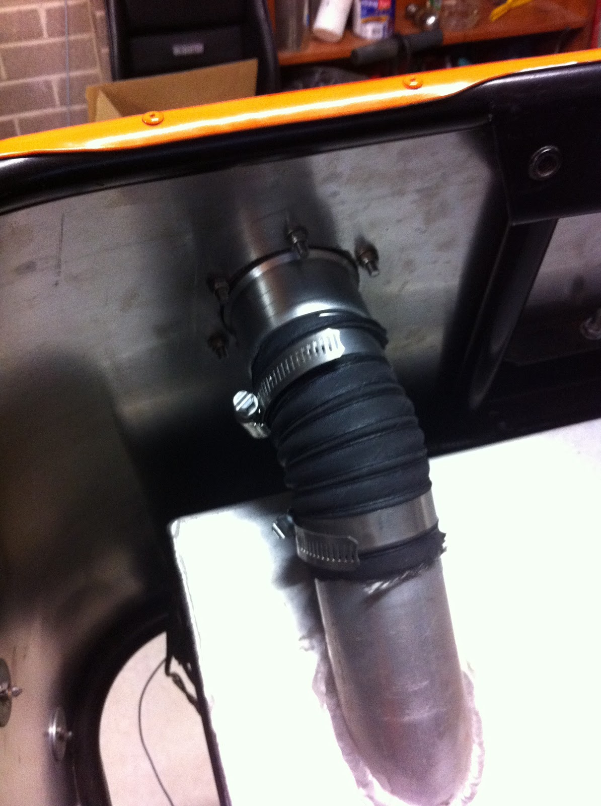
I want to run a closed cooling system, so I needed to fit a breather/expansion tank. This will catch overflow under pressure, and release it back into the system when the pressure lowers and creates a vacuum. Its a shiny aluminum 1 litre tank, and it will have lines in from the bleed, EGR and radiator cap. I will feed back into the thermostat inlet on the block. I have it mounted on a fabricated bracket up front under the nose cone as I don't expect to have to open it to often. I will probably mount a small catch tank under it as well.
Sunday, July 10, 2011
Cooling System
A very productive day has been spent connecting up all of the cooling system hoses. I am using the stock water manifold on the back of the Duratec block as I am running out of budget and could not afford a custom water rail. The photo to the right shows the heater outlet sealed off (yes I will be cold in winter!) and the bleed line is plumbed back to the left side of the car where the expansion tank will be installed on the scuttle. I have since changed the screw clamp for a stock Ford spring clamp.
Next I needed to route the water outlet from the manifold back to the right side of the block and down the front to the radiator. A good look through the CBS Online catalogue in the UK solved this problem both quickly and elegantly. I can't recommend these guys enough. Not only do they have everything you could ever conceivably need to build a kit car, they are not expensive, and this order shipped from the UK on Tuesday and arrived on Friday the same week! The solution was a 180 degree radiator hose bend attached to the manifold.
I then connected this to a 150mm beaded aluminum tube that has a 42mm radiator cap mount welded into it. The design of this system is important as this is to be the highest point in the system meaning all air bubbles should rise to this point. The 150mm aluminum tube is then connected to a modified 90 degree hose that routes the water line down the side of the block. I just now need to add a 580mm beaded aluminum pipe from here down to the radiator top hose. I will mount the water temp sender here as well.
The missing aluminum pipe will be connected to the block with rubber lined P-clips which will stabilise the entire hose system. I may also add an additional brace to the radiator cap tube. I am very impressed with how this has turned our given that it was designed on a web site and ordered without being able to test it first. From here it was down to the front to finish off the radiator outlet to thermostat line. I used a flexible 280mm hose from the radiator outlet, which threads through the steering rack.
This connects to the thermostat inlet hose via a 150mm aluminum beaded connector and three hose clamps. The hose here is 1mm bigger than the connector, so I am expecting leaks under pressure. As the hose just touches the down tube on the space frame, I have added a sacrificial liner to the space frame to protect the hose. Directly above the thermostat inlet is the 18mm inlet that normally connects to the return from the heater. I have been able to salvage the original hose and connectors for this, and after a few modifications been able to connect this hose back to the EGR valve and then on to where the expansion tank will sit. All in all today's work has been very fiddly, but very satisfying as I have been able to design and build something beautiful from new parts, and also salvage and recreate something I need from old parts.
Here on the left you can see where I have clamped off one of the T piece connectors and the main hose runs back under the inlet manifold to the EGR valve. I still need to fit the alternator in under all this, and the cable tie of the rest of the hoses and wiring looms. Next job is to start adding the front fuel and return lines for the fuel rail and the evaporative purge valve. As it was very cold day in Sydney, today was not with out many painful skinned knuckles and cuts on the hands and arms from reaching into tight engine spaces to mount hoses and clamps. I am ordering the fuel filters and regulators this week and hope to get those on next week. I will publish a To Do list soon of what needs to be done pre the first start.
Fuel System - Part 2
Thermal Fan Switch
Long gap between posts. I have been very busy with work and some other projects around the house. I was also waiting for a bunch of parts to turn up for the cooling and fuel systems.
A Thermal Fan Switch is needed to turn on the fan when the water hits a certain temperature. The switch is a Tridon TFS100, which runs a 90-80 range. I had to make up a small 2 wire connector to hook it into the front loom. A bit of teflon tape on the thread and it was in and tightened.
Subscribe to:
Posts (Atom)