Showing posts with label Engine. Show all posts

Wednesday, July 25, 2012

Air Intake

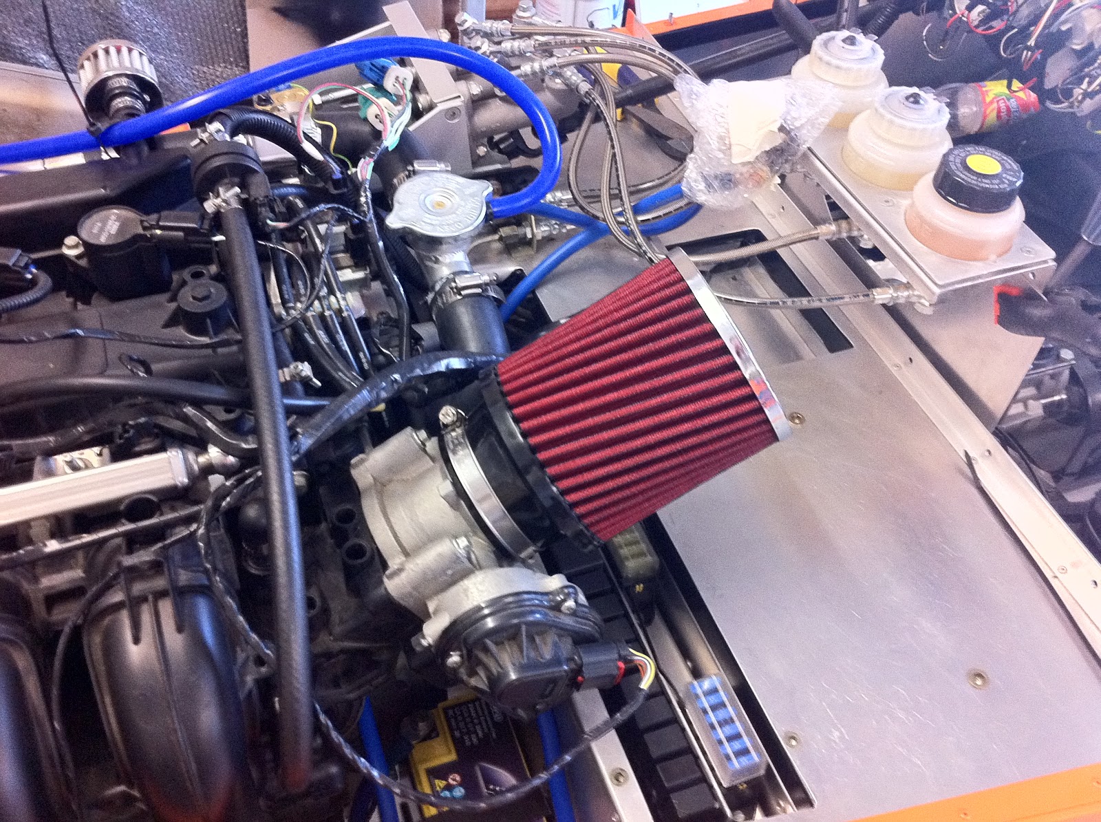
One of the main reasons I failed the first noise test was induction noise. I had a pod filter directly connected to the throttle body, with no air box or resonators. When you nudged the throttle, you could hear it take a breath and gulp air in. On sharp throttle inputs it made very impolite noises, and on wide open throttle it whistled like it had a turbo. To fix all of this I have plumbed in a factory airbox and resonator up in the nose cone, and the routed air piping back to the throttle body. This is the 2.75" aluminum and blue silicone joiners you can see in the photo.  Because of the height of the engine and the intakes on the passenger side, I have had to route this plumbing down the less ideal drivers side, directly above the exhaust headers. To deal with the heat, I have fabricated brackets to keep the plumbing off the headers, and also some additional brackets between the block and the chassis. These are to hold up a heat shield that will keep the headers and the plumbing separate.

The net result is that there is now zero induction noise at idle, and no change in noise for any throttle position....problem solved!

p.s. Also noticed we passed 10,000 page views this week! Thanks to everyone who has followed this build and checked back in on the progress.


Wednesday, June 27, 2012

Engineering - Part 2 (Emissions)

Today was emissions testing. I had to pass the RTA's IM240 test certification which is the equivalent of Euro 2 emissions testing.  Given the engine has no mods and uses the factory ECU, tune and intakes and I have a Euro 3 spec CAT, it should be pretty easy to pass. And it was! It passed with virtually no emissions, with all the key numbers being so far below the max. The test did show up some interesting NOX levels on hard acceleration and a bit of fuel dumping on sudden overrun. Something to work on with the tuner, but its another major milestone passed!

Monday, December 5, 2011

Throttle Mount

As the Duratec uses a drive by wire throttle linked to the ECU, I needed to mount the throttle pedal body somewhere near the existing pedal box. After seeing what other builders had done, I elected to suspend the throttle pedal body on aluminum plate off the back of the pedal box. This took 2.5 attempts to get a mount I was happy with, as the angle and left/right position of the bracket, and the pedal on the bracket is crucial. To far right and the throttle connector fouls the pedal box and frame. To far left and the brake will hit the throttle (ok for heel and toe I guess!).


I also fabricated up from 3mm angle a pedal cover for the throttle which is bolted through the old plastic throttle lever. All of these pieces are bolted up temporarily until I am happy with the position. In sitting in the car I now find the pedal reach is to far, which is ok as I moved the pedal box one adjustment forward....so I guess I am now moving it back one adjustment.


So with the throttle mounted.....I may be able to drive it now?!?!?!?!?!?

Wednesday, November 30, 2011

Since the start....

I figured once I had the car started......another few nights in the garage would see it finished! Another wise Birkin owner (lets call him Maurice!) told me I would be surprised how long these simple finishing tasks would take to complete.........

One of the things I did leading up to the start was have a To Do list that had all the preceding tasks prioritised. Post engine start, I had prepared a list of tasks to finish the car (about 80 tasks), but had not done any prioritising. So many a night has been spent in the garage about to start a task, followed by 60 minutes of pondering (Steve call's it procrastinating ;) the preceding tasks and then walking back into the house having done nothing. For example:

  • To mount the reservoirs and expansion tank on the scuttle
  • Needs the scuttle to be mounted
  • Which means all the wiring has to be finished and checked
  • Which means all the lights have to be fitted and tested
  • Which means the mudguards need to be fitted
  • Which means I need to move the exhaust and finalise the wheel alignments
As a result not a lot of progress. I have managed a few small jobs and these are leading to the chance for me to at least drive the car up the driveway for the first time.


I have modified the pedal box to remove the existing cable activated throttle in order to mount the Focus drive by wire throttle. This involved cutting two parts of the original pedal box off that held the throttle pivot and removing some spacers. Those who have this pedal box will recognise where I have cut it and how neat I have been! This also meant switching the brake pedal pad to the left side of the lever to accommodate the larger throttle. I have since fabricated throttle mount prototype 1 which didn't fit well, and am now half way through prototype 2 which should be the winner. This will allow the throttle pedal to be mounted and a potential drive up the driveway.

I have also removed the Fuel Pressure Regulator and reconnected all the fuel lines and run the engine in that configuration.

 As part of the finishing the wiring, I needed to connect the reverse lights to the reverse switch in the Type 9 gearbox. This is what the switch looked like - missing the connector pins!. So I have purchased a new one and fitted it to the gearbox and completed the reversing wiring. 


On top of all that I have been testing wiring into the dash, and have pulled the main loom off the engine and put rubber grommets into all the body holes, cable tied up the wiring to be in spec, and wrapped all of the engine loom wiring in plastic shielding to protect it in the engine bay. 


I have all the lights arriving this week and will make a concerted effort to get the finger out and get more done.

Monday, October 3, 2011

Engine Start Attempt

As it was a long weekend here, I had been planning for a few weeks to try to get the first start attempt organised for this weekend. After finishing the last few things on my To Do list we ran some electrical checks, then dropped her back on to her wheels. From here we pulled all the spark plugs out to lower compression and then cranked the engine over by hand to circulate some oil. We then cranked the engine over with out any fuel, to make sure it cranked. It did! This means most of the electrical system so far is working with no blue smoke coming out.


We then rolled her out the front, and broke out the fire extinguishers. I put 5 litres of fuel in the tank, and we got ready to fire it up. Turning the key got it to crank, but that was it. A glance at the fuel pressure gauge indicated no pressure. So either we had the filter in the wrong way up, the the FPR incorrectly set up, or the pump lines were wrong. We pulled the line off between the pump and the filter, and cranked it again back into the jerry can. Still no fuel?!? The pump was cutting out fairly quickly, so we surmised maybe there was not enough fuel in the tank, so we added 5 more litres and tried it again. Fuel started to splutter out of the hose! We reconnected it back to the filter and clamped it, then tried it again. No start, but this time the FPR went up to 90psi.....which is double what we need. I adjusted the FPR back down to 42psi and locked it off.


Put the key back in and cranked it over......


:)   Very happy!


It starts easily, runs very smoothly and revs nicely. Its fairly quiet with the muffler I have fitted. I need to reorganise the cooling, but it pressurised OK and nothing leaked. Best of all the fuel system worked perfectly (once we had enough fuel in it). Its hard to believe I have managed to pull together a bunch of parts from all over the world and combine them into a single working unit.


This is a major milestone as I can now engage the engineer to start certifying it for rego, and I can also start putting the finishing touches on it such as the windscreen, roll bar and the lights. 


Many thanks again to Steve who assisted with the troubleshooting and shared in the elation of the first start (although no feet in the video as he was shooting it on the phone!)


Pod Air Filter

I didn't get the factory air box and air filter from the donor Focus, so I have fitted a pod filter in the interim to let me start it and get it engineered. Depending on the induction noise I may use it for rego........Looks cool though :)

Fan belt

Fitting the fan belt means I have the alternator 100% fitted, and the idler pulley refitted. The belt is a 5PK1260, which I cut one rib off using a Stanley knife. Being 4 ribs only means I can move it backward or forward for adjustment as the crank pulley and idler pulley are both 6 ribs.

Tuesday, August 16, 2011

Oil Pressure Sender

The addition of the M12x1.5 adapter meant I could connect the VDO oil pressure sender into the horizontal Raceline oil filter adapter. I fitted the Raceline adapter mainly to get the oil filter up inside the bottom line of the chassis, rather than having it hang down next to the sump. Less to get knocked off. I just need to pull the wiring to it now and connect it to the body loom.

Adapters

In order to fit the VDO senders for oil pressure and water temp, plus finish of the fuel regulator I needed to source some adapters. This resulted in a lot of Google research and I ended up at the Speco Automotive site. From top to bottom I got a M12x1.5  - 1/8NPT adapter for the Oil Pressure sender, a 1/8NPT (female) to 1/8BSP (male) adapter to fit the final hose tail to the service port on the SARD fuel regulator, and a 32mm radiator hose adapter that takes 1/8NPT VDO water temp sender. I fitted all of them together on the bench using Permatex thread sealer, before cleaning up and fitting to the car.

Monday, June 6, 2011

Finishing the Engine

With the drivetrain finished, we could move onto to getting the engine physically finished. This involved putting back on all the parts that were removed while prepping the engine for installation.  Given the tight fit in the engine bay, its important to finish off areas that will be hard to get to later on. This meant installing the supply wiring for the battery, and all of the wiring to the starter motor. I have decided to add a master cut off switch for the electrical system, so have routed two cables from the battery and starter motor up to the scuttle where the master cut off switch will be mounted. We have also prepped the connections for the alternator, and cable tied the rest of the loom into its final location.


With the electrical work done we could start refitting the inlet manifold, crank case vent, throttle body and the vacuum hoses and sensors. The inlet manifold (right) is a "very" tight fit between the chassis, starter motor and idler pulley. It also has two dowel pins that need to be lined up in the head to locate the gaskets, and behind it are the water transfer hose that needs to be locked in place, and the crank case vent hose needs to be reconnected and clamped. Luckily I had Steve along to help, and with his double jointed wrists and fingers we were able to reconnect all of this with the minimum of blue language and only a little blood .... Steve's! (obligatory stunt foot in photo near wishbone).


From here we were able to refit the throttle body, and all of the other vacuum, hoses. The engine is now ready for the cooling hoses to be hooked up once the radiator is fitted. That just leave the wiring to be finished, the fuel system to be installed and the exhaust to be fitted before we think about firing it up for the first time.

Tuesday, May 10, 2011

Engine & Transmission Removal No.4

No I didn't miss one....Engine & Transmission Removal No.3 occurred in the end of the Clutch post. I am starting to lose track of the Removals and Installs, so I thought I would do a quick summary of each one. Maybe someone can learn from these, and avoid having the same issues I have had.


Interesting the first install took about 4 hours. The first removal took 1 hour 18 mins. After that I have been averaging 42 - 45 mins for both although the engine is bare. I expect it to be somewhere up to 3 hours to install or remove once the car is completed.
  • Install first time
  • Removal number 1 for modification to bell housing for new starter motor
  • Install 2nd time
  • Removal number 2 to fix sump leak
  • Install 3rd time
  • Removal 3 for clutch leak and needing to reset the CSC preload
  • Install 4th time
  • Removal number 4 to retrieve and replace the burst clutch hose from within the bell housing
The last removal was a world record of 1 min and 11 secs and I took a video of it!

Check it out here! (have the sound up a little)


Tuesday, April 26, 2011

Engine & Transmission Removal No.2 (Part 3)

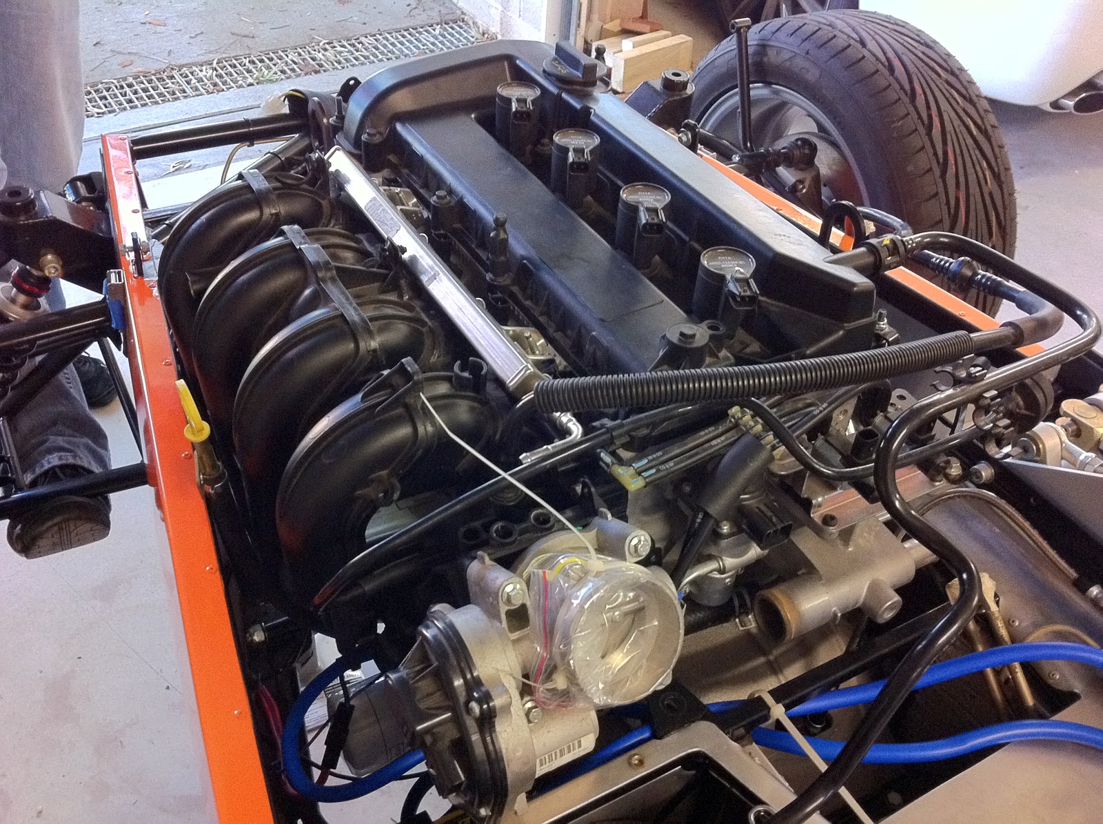
After letting the motor sit for 24 hours with the oil in it, no new leaks have appeared. In contrast to two days ago, oil leaked almost immediately after I filled the engine, I would say I have fixed the problem (that I caused myself!). So today was spent refitting the engine and gearbox back into the chassis. The photo to the right (with the obligatory foot from my mate Steve!) shows the engine back in place. We were on a roll so we fitted the manifold (had to jack the rear of the gearbox up to get the back manifold bolt in) and the 4 - 1 collector, the short throw gear lever and the billet aluminum gear knob. While waiting for the sump sealant to cure yesterday I finished all the body wiring off. This included routing and securing the rear wiring loom, as well as the front body loom in the engine bay. I also tidied up and secured all the under dash loom wiring in preparation for refitting the scuttle. It was nice to finish the weekend off that started so badly with some progress.

Sunday, April 24, 2011

Engine & Transmission Removal No.2 (Part 2)

After letting the sealant cure for 24 hours, I refilled the engine with oil. It still leaked! Although this time I could see that it was seeping out in an area where I knew I had not put any sealant close to the outside of the sump, as the bolt holes tracked further in. 


Before I stripped it back down, I compared the photos I had taken the previous day of the freshly disassembled parts and compared these to the manual, and to the factory sump I still had. This showed me that the Raceline sump and the factory sump were very different in there structure, specifically in the area where it was leaking. By following the Ford manual for applying the sealant I had unwittingly put the sealant in a spot where it would never be sealed. I dug around for the Raceline sump instructions, and sure enough there is a small photo showing where to apply the sealant (you need to look hard!). This was different to what I had done. 


So I drained the oil and popped the sump off expecting to see some sealant still sitting in a bead because it hasn't been sealed (photo on the left), and a clean part of the flange on the sump where it didn't get sealed at all. (photo on the right)


Lets call this a tada moment because it was exactly as I expected!! 


So an hour was spent cleaning off the old (yesterday's) sealant and I was ready to reapply correctly as per the Raceline instructions. I also made the nozzle hole larger on the sealant tube and improved the flow of sealant to make it easier as I was still using the previous tube of sealant. 


Something still had to go wrong, so as I refitted the sump with the new sealant, the thimble seal for the oil pickup dropped out twice, firstly jamming the sump from fitting, and secondly by dropping into the bowels of the up turned engine! Once I refitted the thimble seal, I got the sump on cleanly, and torqued the bolts up. I also replaced the troublesome bolt with one 5mm shorter (which i had previously tested) to make sure I was getting torque on the mating face and not on the the end of the bolt bottoming out in the thread. The end result was that I had a nice even ripple of sealant right around the join.


So maybe this time I have got it? Again I will let the sealant cure for 24 hours before refilling the engine with oil and testing for leaks. So while frustrating, its far better understanding why it happened. Lesson learnt....read ALL the manuals for the job you are doing!


Hopefully part 3 of this will be how it tested dry and I could refit the engine, and not a for sale notice!


Saturday, April 23, 2011

Engine & Transmission Removal No.2 (Part 1)

So I have now taken out the engine and transmission for the second time. This blog is called Part 1, as I will write Part 2 when I work out whether I can put it back in a couple of days from now. Why is it out? It has a very small oil leak from the front left of the sump seal with the block. The good news is that I broke my previous record for removing a bare engine of 1 hour 18 mins. I can now remove the engine in 42 minutes flat. This has also led me to a redesigned engine and gearbox mounting trolley as can be seen in this photo.


On initial inspection the oil is coming out from the corner bolt on the timing chain cover all the way back to the 3rd sump bolt behind the dipstick plug. All up this is over about 6 inches of distance, although its hard to tell whether its just leaking in one spot and tracking to the lowest spot before dripping. So up onto the engine stand. This also meant removing the gearbox, and the clutch plates to get it mounted which is a bugger. First job is to drain the oil and remove the sump.


Removing the sump showed me the first problem. The bolt (which is No.1 in the bolt pattern) directly to the right of the drain plug was not tight. This is a 25mm bolt supplied by Raceline for the sump, which is longer because the sump flange is thicker here. No amount of tightening gets this any tighter???. Once I had the sump off, this showed that perhaps this was the main problem because the RTV sealant either side of this bolt had not properly sealed as it would when fully torqued. This can be seen at the top of this photo, just to the left of the oil filter.


The other problem I notice is that I have sealant everywhere, including nearly completely blocking one of the main oil galleries into the sump. One thing that has changed since I first fitted the sump is that I have managed to source the actual engine build manual from Ford for the Duratec. As a male, reading any manual is usually considered optional and only then after trying to do it without the manual first. What the manual has showed me is that I did not layout the RTV sealant on the right path, and I probably used to much as I had it beaded at about 7mm and the manual calls for a 2.5mm bead. So yesterday was spent removing all the old sealant from both mating faces and polishing these back to new so I could reseal them. I sourced some Loctite 5900/598 RTV sealant this morning and set about refitting the sump. I prepped the nozzle to create a thin 2.5mm bead, however getting a consistent bead from a toothpaste size tube is nearly impossible by hand . Five minutes later, after lots of swearing and having sealant all over me, I had managed to layout a passable thin bead on the correct path. I refitted the sump and put the bolts back in. Tightening them to the correct torque and using the correct tightening sequence I quickly had it back together. EXCEPT for the problem bolt, which is still not tightening, even though it tightened OK without the sump flange in place. I figured there is something wrong with the top of the thread, and quickly grabbed an M8 bolt that was 10mm longer. This bolt went in OK and I was able to torque it correctly and see the sump pull in tight at this point.  Hopefully the bead of sealant I have laid is OK and the problem bolt was the only issue. 


So what I have I learnt from this. LOTS!

  • Where possible, try to add any fluids before you fit any major components to make sure you have a seal. The engine oil could have been added weeks ago when the finished engine was still on the stand, and I would have noticed the leak then. I even thought about doing it but never got around to it. I was lucky that I didn't start adding other engine components as I waited 48 hours after adding the oil to see if it leaked (it took the 48 hours to show up and even then it wasn't much).
  • Get the right manual for the bit you are doing and read it thoroughly. Had this not leaked and I had run it with the oil gallery blocked I hate to think what could have happened to the engine.
  • Always have spare bolts for the job you are doing, and also having other lengths of the same size bolt can come in very handy. My fastener collection for this car is growing daily.
  • When applying sealant, make sure its done with an applicator that allows constant pressure such as a syringe/plunger or caulking gun. 

I will let the sealant cure for 24 hours before adding the oil again. I will then let it sit on the stand for another 48 hours to see if loses any more oil. Hopefully then Part 2 of this particular topic will be about reinstalling the engine and not a for sale notice for a half built Birkin!

Sunday, April 17, 2011

ECU

I have been pondering where to place the ECU. I have seen photos of all sorts of different mounts including low on the firewall, above the bulkhead in front of the scuttle and under the scuttle in the passenger footwell. The 2009 Focus ECU that I have is different to earlier Focus ECUs in that it uses three plug connectors rather than two, and these are on the top rather than on the back. They do however require a cable entry from the right. Also on the plus side, this ECU is considerably smaller, thinner and lighter. Given the Birkin chassis for the Duratec engine has a much deeper fusebox (cutting into the passenger footwell), I took some measurements and came to the conclusion I could mount the ECU in the bottom of the fusebox, below the fuse and relay frame. This position is good as I don't trust the dust seals on the connectors so I was skeptical about mounting the ECU in the engine bay. Ford obviously agree with me because the ECU came out of a heavily sealed plastic box in the Focus.


I started by putting the ECU in the footwell and positioning it for marking up the mounting holes.
From here I drilled through the footwell into the fusebox. To isolate any metal on metal vibration on the ECU, I lined the back of it with thin neoprene where it sat flat against the fusebox side. I also machined up some thin aluminum spreaders to use in the footwell rather than washers as the aluminum at the end of the footwell is quite thin so I wanted to spread the load out. I was able to connect up the rear harness connectors and lay these in the bottom of the fusebox before fitting the fuse and relay frame above it. This will make the relays and fuses easily accessible from the top of the fuse box. 


Tuesday, April 5, 2011

Starter Motor

The thing that caused me to have to remove the engine and transmission is now fitted. Funny how something that only needs two bolts and fits into a pre cut slot in the bell housing can take nearly two days to fit. But now its bolted in and fits perfectly. As this starter motor didn't have the foam seal around the bell housing slot, I have replaced this with a thick bead of silastic. I also fitted the engine oil filter which can be seen below the starter motor. 

Monday, April 4, 2011

Engine & Transmission Removal No.1

A wise man told me that before I finished the build I would take the engine out and reinstall it several times.....so 2 weeks after it was installed, here is the first removal. This was bought about for a few reasons. Firstly, I had to replace the starter motor with a Mazda unit to match the lightened flywheel. This new starter motor had some alloy shoulders that prevented it being mounted on its posts and engaging correctly with the bell housing. Secondly, I needed to measure where the hole in the transmission tunnel would be for the electrical loom going into the fuse box. Lastly I wanted to add the gearbox oil and check the seals. This removal only took a little over an hour and a quarter, but I imagine it will be a lot longer with full electrical, a fuel system and a cooling system all connected.


Here is the bell housing where the starter motor mounts. It needed to be notched and filed down on the two corners where it mates with the engine block. In removing the gearbox I also found that one of the CSC bolts had sheared off (over torqued to many times while fitting), so I replaced all three of these to be safe. Half an hour of filing and refitting the starter motor and I had the notches I needed. From here it was simply a case of refitting the gearbox to the motor (easier done with two people) and re-torquing all of the bolts on the bell housing. 


While I had the gearbox on the bench, I filled it with oil (Castrol Syntrax 75W90 fully-synthetic). This is far easier than doing in the car and I dread having to get the filler plug out from within the passenger footwell in the future.

I had also marked up a 50mm hole in the side of the transmission tunnel before the engine came out, so I used a hole saw to cut this out from within the fuse box. This will have a sealed grommet fitted one the ECU is mounted and the cables are routed. I also got to fix up a few bits of bodywork in the engine bay that needed to be modified, trimmed and riveted after the first engine fitting.

So after all those mods and tweaks, the engine and transmission went back in (in an hour and a quarter). I now know what sequence to put the mounts on to get the best fit, and which cross braces and brackets to remove. Only problems remaining are that the main bolt for the flexible gearbox mount is not lining up, I have small oil leak from the seal at the back of the gearbox output shaft when the car is inclined. I will deal with those and fit the starter motor tomorrow.

Monday, March 21, 2011

Engine & Transmission Installation

Time to fit the engine and gearbox! After attaching the finished gearbox to the engine, we lifted the front of the car up and slid the engine/gearbox combo underneath (these were on a wheeled trolley). It's then a series of incremental steps of lowering the car and easing the engine back into the bay so the gear box feeds into the transmission tunnel. We removed the lower mid chassis braces to assist in positioning the gearbox, and we also removed some of the cooling system and the idler pulley from the engine to allow it to fit.


You will notice a pair of feet or legs appearing in these shots. These are artistically provided by Steve (Shireman on OzClubbies) who has decided that all shots should have his feet featured in them. This exercise would have been impossible without his assistance as the constant positioning and repositioning of the car and engine needs plenty of carefully applied brute strength. The photo to the left is about halfway through the install with the car being lowered. When I do this again I would be inclined to remove the gearbox support subframe from the chassis as well and attach it later (reverse of how we actually did it).
Once the engine is fully seated in the engine bay, its a case of lining up the engine mounts (previously attached to the engine) with the mount points and then bolt these up. Its amazing that the entire engine is supported by only 4 hex bolts (mounts to block) and two large bolts (mounts to chassis).


After some four hours, about an hour of which was spent laying on the floor trying to located and secure the flexible gearbox mount bolts, the engine was fully installed. From here the pieces that were removed were added, the chassis cross braces were reinstalled and the hose for the clutch was routed across towards the distribution point for all of the hydraulic lines.  Engine and gearbox in!. This was a great step as it really now feels like its a car, and I can see what needs to be done to complete it.  Thanks again to Steve for skinning his knuckles and sliding around on the dirty garage floor underneath the car securing bolts all in the name of getting the car finished!


(One more photo from another angle because it looks so cool now!).


Lessons learnt:
- Remove the gearbox support from the chassis
- Remove the old manifold studs first.
- Have the engine on its trolley as close to mount height as possible.
- PUT OIL IN GEARBOX BEFORE YOU INSTALL!!! (its a pain to do it once fitted)