
Thursday, June 16, 2011
Fuel System - Part 1
Front Brake Lines


Radiator


Tuesday, June 14, 2011
Horn

Ignition Immobiliser
 One of the great things about building a car like the Birkin, is you join a community of like minded people, who participate in the build process with you by either offering assistance (spilling blood in the workshop), or advice and feedback. A fellow Birkin owner, Maurice sent me some ideas the other night that I was able to incorporate into my build and solve a problem I had yet to confront.
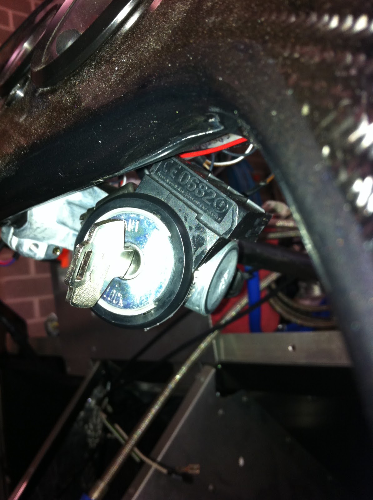
The Passive Anti Theft System (PATS or immobilizer) coil is a black plastic ring that fits around the ignition barrel in the Focus. It is wired back to the dash cluster and ECU, and it reads the immobilizer code in the key and allows the engine to start. The issue here is that I have added an aftermarket ignition which is much smaller than the PATS coil. I had considered mounting it somewhere else under the dash, or behind the centre console, and then just touch to key fob to it as I start the car. The problem with that approach is then I have to have the two keys separate which means I would ultimately lose one.

Maurice's solution was elegantly simple and very effective. He suggested using a thin aluminum sleeve with a cut through it, fitted over the ignition barrel. The PATS coil is then fitted over the aluminum sleeve which gives a snug interference fit, and allows the PATS coil to sit flush with the ignition barrel. The whole thing is then tightened together using a stainless steel hose clamp. Great solution. Thanks Maurice!
Monday, June 6, 2011
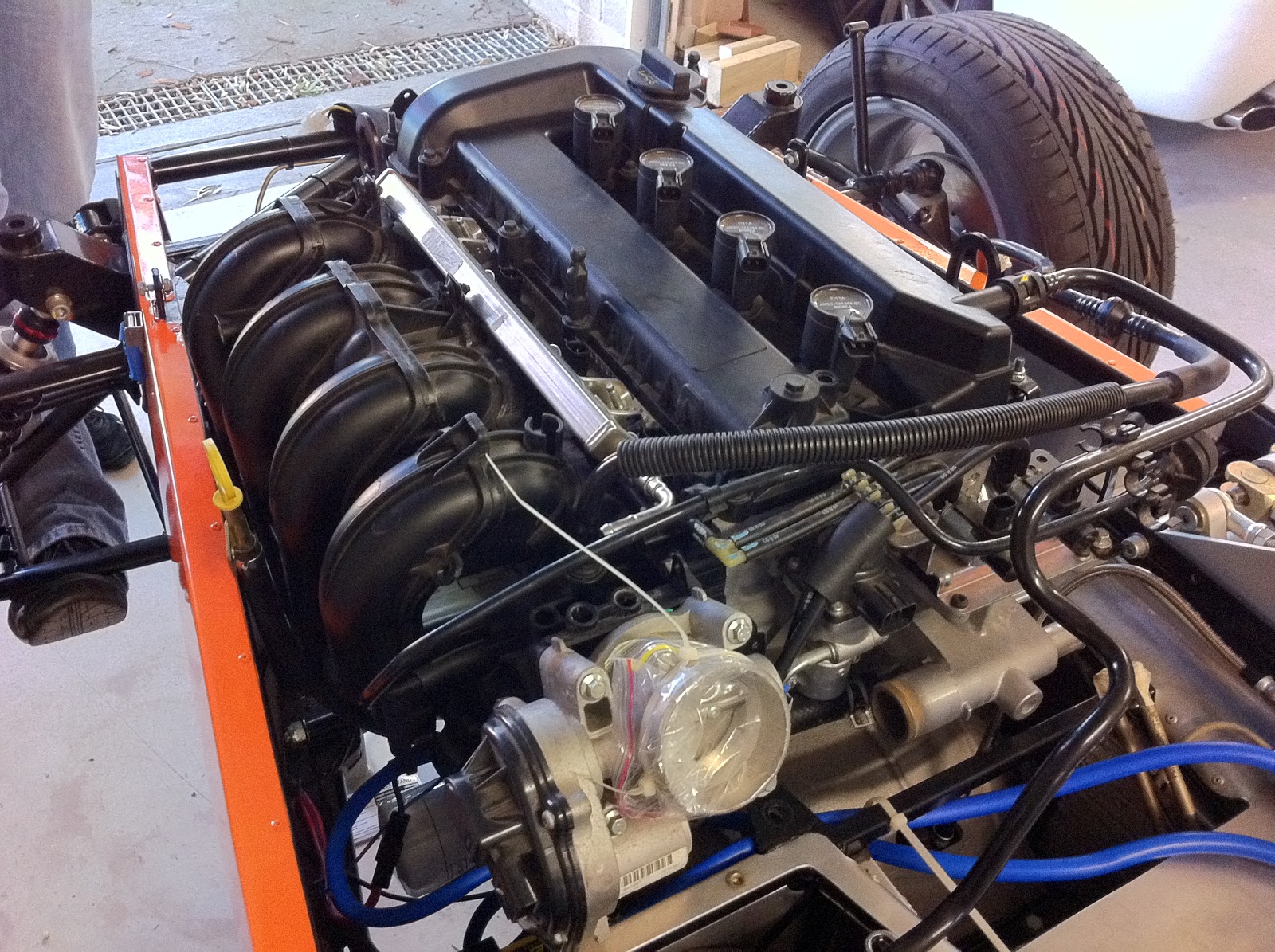
Finishing the Engine


Monday, May 30, 2011
One Prepared Earlier .....

Sunday, May 29, 2011
Rear Stabilisers

These weren't overly complicated to fit, however it was good to have Steve's car here as a "template" to check the alignment and final configuration of washers and conical spacers. This means the rear suspension is finished and I can start working on the fuel system.

Saturday, May 28, 2011
Differential

With the handbrake pivot in and connected, we were able to finish off the drivetrain. This meant fitting the diff which had been sitting on the bench finished for some time now. The diff is a 4.1 Subaru LSD. We lifted it into position (easier with 2 people), and secured the two rear bolts. There was an issue with the front mount fouling on the chassis, but this was easily remedied by removing a washer from each side on the two rear bolts, which took the diff back slightly. We then had to lift the front of the diff and insert the 4 alloy spacers and bolts to secure the front of the diff to the chassis.

All in all, not to hard a job, and only a few cuts on the hands and limited swearing. This then allowed the prop shaft to be pulled back against the diff flange to be bolted up. The prop shaft is secured to the diff by 4 high tensile bolts. This meant the engine, clutch and gearbox are now connected to the diff for the first time. So far so good! Next job was to fit the half shafts. This meant disconnecting the rear uprights, and then tapping the half shafts in to the diff until they clip in. It was then just a matter of feeding the drive splines into the hubs, remounting the uprights, and securing the half shafts to the hub with the hub nut. This requires huge torque to secure the hub nut. We were also able to finish off securing all of the upright rose joints including fitting the R clips. Once we had the wheels back on, the drivetrain is complete from engine to rear wheels. The moment of truth! Does the clutch work properly??


We popped the gear lever in to second and made sure we had everything binding, then Steve pushed the clutch in. If the clutch is actuating properly, I should now be able to spin the prop shaft and diff independently from the engine. But it didn't spin!!!!. With a sinking feeling of having to remove the engine and gearbox again to correct the clutch we stood silently. It then hit me that maybe the clutch plate had frozen between the pressure plate and flywheel, as it had been sitting in that state for some while. So again Steve depressed the clutch and I rocked the prop shaft back and forward. After a bit of grab, it spun freely!!! The clutch appears to work and is correctly adjusted. This means we have everything now connected and working from the motor back to the rear wheels. A huge step forward and a very satisfying job in only 3 hours.
Once again, this job could not have been achieved without the assistance of Steve (see foot to the left) who added the extra muscle and brain power to get this task finished relatively painlessly (he got cut hands today). I will ask him nicely tomorrow if I can post a photo of his Birkin up here so people can see what a real one looks like (finished!).
Slowly but surely, the collection of parts on the floor in boxes, on the shelves and in the cupboards and drawers around the garage is finding its way on to the car, as we edge closer to engineering and rego.
Ignition
 As the original Focus ignition won't be used (just the PATS reader), I needed to find, buy and fit an ignition barrel and steering lock. After lots of questions to other Clubbie drivers I was pointed to Repco to get a replacement Nissan barrel. The actual part is a NIC301 from Nice Products. It has a 33mm housing which fits perfectly onto the Birkin steering column and the steering lock works a treat (perfect for ADRs). I had to remove the tacho and one of the indicator lights to fit it. The best part is the wiring loom connector fits it perfectly with no mods required. I have not decided yet whether I will fit the PATS reader on the barrel, or hide it somewhere else behind the dash. This picture is taken from the side under the dash (the scuttle is still off at the moment until the wiring is completed and the car starts).
Thursday, May 26, 2011
Handbrake
My missing parts arrived today!. Thanks to Brenton at Meridian Motorsport for maintaining the pressure on Birkin to deliver, and for putting up with my constant email requests for updates.


The handbrake pivot should be one of the first parts fitted in the build, as it is the key to most of the back end going together. Once this pivot is fitted, the diff can go in as well as the half shafts, the rear brake lines and the fuel tank. A lot hinges around this one bit of metal! Before I fitted it, I drilled out the clevis holes another 0.5mm and shortened the split pins (thanks Mark!). I greased the pivot bush, and then used an M8 bolt and nyloc to secure it (not to tight as it needs to pivot). Its then a simple task to fit each of the cable eyes into its corner and secure with a clevis pin and split pin. A few more minutes of adjustment to the cable housing length, and the pull adjuster on the handle and it was clamping the wheels. Now hopefully I can finish the back end of the car.
Saturday, May 21, 2011
Braided Hoses
 I have taken delivery of all new braided stainless steel hydraulic hoses to replace the standard rubber ones. These will replace the clutch slave cylinder hose plus the 4 outboard brake hoses. They are made using BrakeQuip equipment and are clear PVC covered with the correct ADR markings. The photo to the right shows a comparison of the old black rubber hose and the new ones. I had always intended on replacing them at some point, just not this early. Professional inspection of the blown factory clutch hose showed that it had barely been crimped with only about half a millimetre of bite on the end of the rubber hose. I feel much more comfortable with all new hoses on the car.
Many thanks to Greg at Redback Motorsport of Kirrawee for sorting the new hoses. Its brilliant to have such a great motorsport shop so close to home, with people so knowledgeable and keen to help!
Thursday, May 12, 2011
Broken Clutch Hose
 After the clutch hose blew out, I have decided to replace all the stock rubber hydraulic hoses on the car with stainless steel braided lines. This means removing the outboard lines to the front and rear brakes, as well as removing the remaining clutch coupling which was still attached to the CSC in the bell housing (which means removing the engine and gearbox ...... again!). This photo (pardon the hand) shows what's left of the hose coupling that was in the bell housing. The hose let go from the top. The new ones are coming from Redback Motorsport at Kirrawee.
At least with new braided hoses on all hydraulic lines I will never be worrying about this sort of problem occurring as I head into a corner deep under brakes!
Tuesday, May 10, 2011
Engine & Transmission Removal No.4
No I didn't miss one....Engine & Transmission Removal No.3 occurred in the end of the Clutch post. I am starting to lose track of the Removals and Installs, so I thought I would do a quick summary of each one. Maybe someone can learn from these, and avoid having the same issues I have had.
Interesting the first install took about 4 hours. The first removal took 1 hour 18 mins. After that I have been averaging 42 - 45 mins for both although the engine is bare. I expect it to be somewhere up to 3 hours to install or remove once the car is completed.
Interesting the first install took about 4 hours. The first removal took 1 hour 18 mins. After that I have been averaging 42 - 45 mins for both although the engine is bare. I expect it to be somewhere up to 3 hours to install or remove once the car is completed.
- Install first time
- Removal number 1 for modification to bell housing for new starter motor
- Install 2nd time
- Removal number 2 to fix sump leak
- Install 3rd time
- Removal 3 for clutch leak and needing to reset the CSC preload
- Install 4th time
- Removal number 4 to retrieve and replace the burst clutch hose from within the bell housing
The last removal was a world record of 1 min and 11 secs and I took a video of it!
Check it out here! (have the sound up a little)
Tuesday, May 3, 2011
Clutch


So I guess what I will do now is just pop the engine and gearbox out again, and fit a braided hose before bleeding the clutch again. I will also need to ensure I have enough adjustment in the CSC spring to get a reasonable take up point.
Subscribe to:
Posts (Atom)