
Tuesday, August 16, 2011
Thermal Fan Switch - Part 2
Tuesday, July 26, 2011
Fuel System - Part 4
 To finish the back of the fuel system off I need a few parts. Because I didn't use the Focus in tank pump, I have to add an external fuel pressure regulator, and obviously I also need a high pressure filter. The filter is an OEM part from Nissan used in the Sylvia and Pathfinder, and purchased more so because it fit inside this cool-> alloy bracket. It is mounted on the bulkhead behind the passengers seat. I have also purchased a SARD fuel pressure regulator. Because the Duratec uses a returnless fuel rail, I need to regulate pressure after the pump, then return excess fuel directly to the tank. This means the SARD regulator needs three barbed connectors (pump, rail, return). I have grabbed some Permatex thread sealant to ensure I have no leakages as well. The first two connectors went in easily and are now sealed.

left of the diff, and a return to the tank (the top connector on the in-tank fuel pump with the yellow cap). You can also see the line from the middle of the pump to the charcoal canister, and in the last photo, the line from the canister that goes down and picks up the line to the front of the car which is to the EVAP valve. So to finish the fuel system I need the fuel regulator fitted, plumbing for this and a connector for the fuel pump wiring.
Fuel System - Part 3

manifold to get it lower and tighter.

The fuel lines are all rated to three times the pressure of the pump (about 143 psi max) and everything is finished off with stainless fuel line clamps. Thats the front bits finished.
Charcoal Canister


Reservoir Lines

Breather Tank

Sunday, July 10, 2011
Cooling System


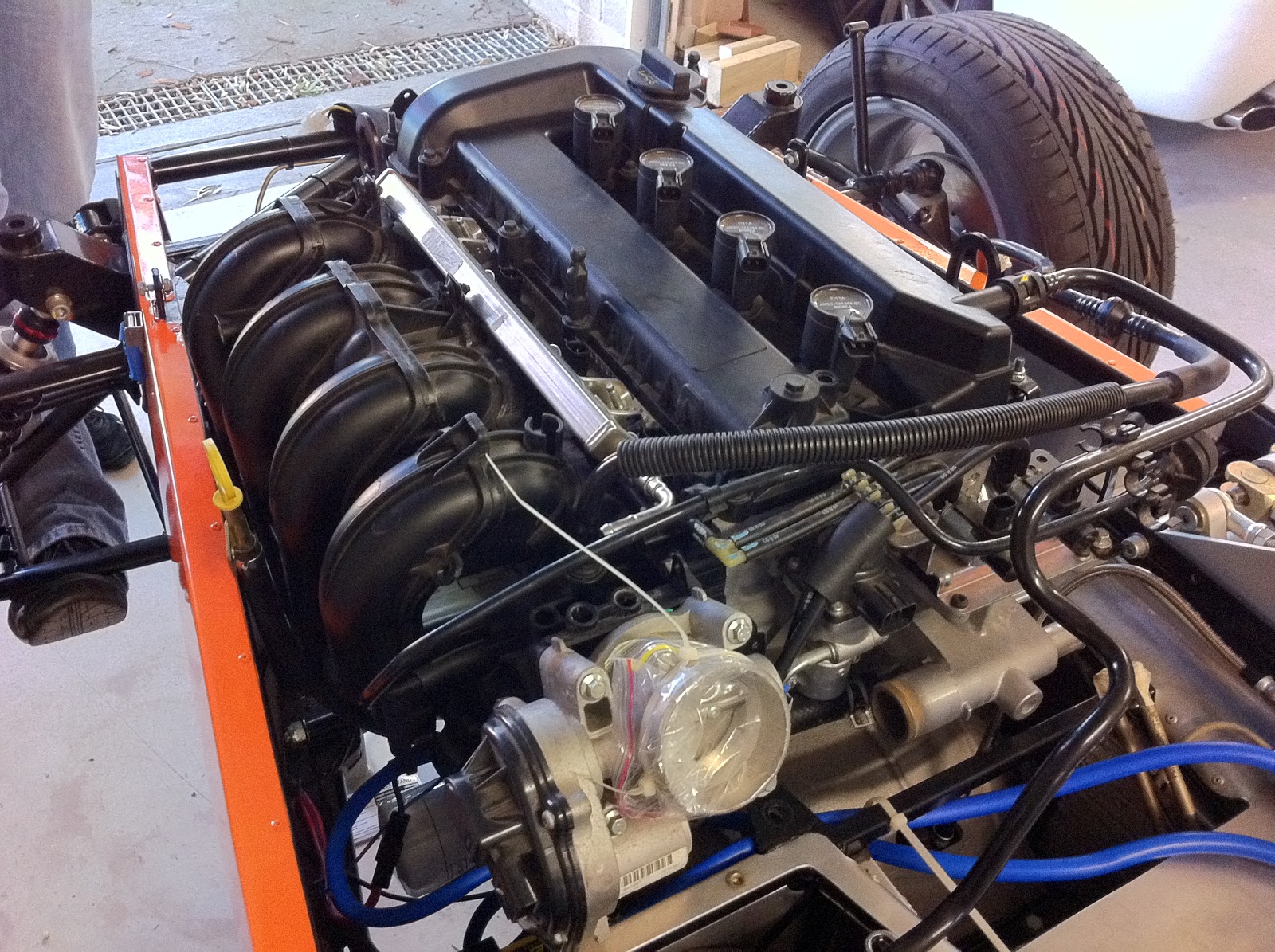
Next I needed to route the water outlet from the manifold back to the right side of the block and down the front to the radiator. A good look through the CBS Online catalogue in the UK solved this problem both quickly and elegantly. I can't recommend these guys enough. Not only do they have everything you could ever conceivably need to build a kit car, they are not expensive, and this order shipped from the UK on Tuesday and arrived on Friday the same week! The solution was a 180 degree radiator hose bend attached to the manifold.

I then connected this to a 150mm beaded aluminum tube that has a 42mm radiator cap mount welded into it. The design of this system is important as this is to be the highest point in the system meaning all air bubbles should rise to this point. The 150mm aluminum tube is then connected to a modified 90 degree hose that routes the water line down the side of the block. I just now need to add a 580mm beaded aluminum pipe from here down to the radiator top hose. I will mount the water temp sender here as well.

The missing aluminum pipe will be connected to the block with rubber lined P-clips which will stabilise the entire hose system. I may also add an additional brace to the radiator cap tube. I am very impressed with how this has turned our given that it was designed on a web site and ordered without being able to test it first. From here it was down to the front to finish off the radiator outlet to thermostat line. I used a flexible 280mm hose from the radiator outlet, which threads through the steering rack.

This connects to the thermostat inlet hose via a 150mm aluminum beaded connector and three hose clamps. The hose here is 1mm bigger than the connector, so I am expecting leaks under pressure. As the hose just touches the down tube on the space frame, I have added a sacrificial liner to the space frame to protect the hose. Directly above the thermostat inlet is the 18mm inlet that normally connects to the return from the heater. I have been able to salvage the original hose and connectors for this, and after a few modifications been able to connect this hose back to the EGR valve and then on to where the expansion tank will sit. All in all today's work has been very fiddly, but very satisfying as I have been able to design and build something beautiful from new parts, and also salvage and recreate something I need from old parts.

Here on the left you can see where I have clamped off one of the T piece connectors and the main hose runs back under the inlet manifold to the EGR valve. I still need to fit the alternator in under all this, and the cable tie of the rest of the hoses and wiring looms. Next job is to start adding the front fuel and return lines for the fuel rail and the evaporative purge valve. As it was very cold day in Sydney, today was not with out many painful skinned knuckles and cuts on the hands and arms from reaching into tight engine spaces to mount hoses and clamps. I am ordering the fuel filters and regulators this week and hope to get those on next week. I will publish a To Do list soon of what needs to be done pre the first start.
Fuel System - Part 2

 The stock Birkin fuel filler is pretty naff, and by all reports it leaks when the fuel sloshes about the tank when its full. One of the first extra parts I purchased when I got the kit was an Aero style lockable filler and cap. Its brushed satin aluminum, and has an unleaded fuel flap inside which is needed for ADR. I have only just fitted it now as I needed to replace the filler hose with a flexible one, and the fuel tank needed to be in its final position and strapped down. To fit it, I needed to expand the size of the hole in the body to about 64mm diameter. Looks pretty cool!
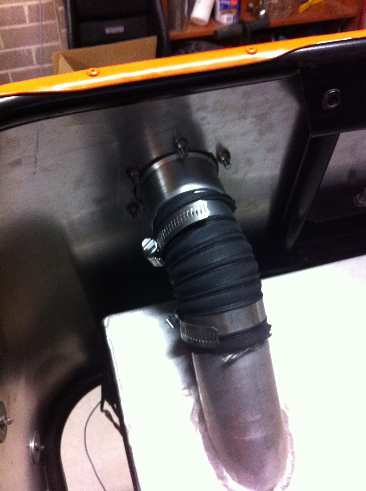
Thermal Fan Switch

A Thermal Fan Switch is needed to turn on the fan when the water hits a certain temperature. The switch is a Tridon TFS100, which runs a 90-80 range. I had to make up a small 2 wire connector to hook it into the front loom. A bit of teflon tape on the thread and it was in and tightened.
Thursday, June 16, 2011
Fuel System - Part 1

Front Brake Lines


Radiator


Tuesday, June 14, 2011
Horn

Ignition Immobiliser
 One of the great things about building a car like the Birkin, is you join a community of like minded people, who participate in the build process with you by either offering assistance (spilling blood in the workshop), or advice and feedback. A fellow Birkin owner, Maurice sent me some ideas the other night that I was able to incorporate into my build and solve a problem I had yet to confront.
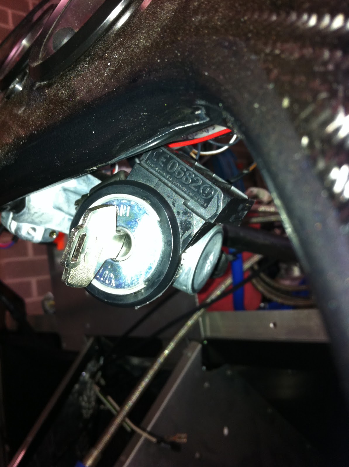
The Passive Anti Theft System (PATS or immobilizer) coil is a black plastic ring that fits around the ignition barrel in the Focus. It is wired back to the dash cluster and ECU, and it reads the immobilizer code in the key and allows the engine to start. The issue here is that I have added an aftermarket ignition which is much smaller than the PATS coil. I had considered mounting it somewhere else under the dash, or behind the centre console, and then just touch to key fob to it as I start the car. The problem with that approach is then I have to have the two keys separate which means I would ultimately lose one.

Maurice's solution was elegantly simple and very effective. He suggested using a thin aluminum sleeve with a cut through it, fitted over the ignition barrel. The PATS coil is then fitted over the aluminum sleeve which gives a snug interference fit, and allows the PATS coil to sit flush with the ignition barrel. The whole thing is then tightened together using a stainless steel hose clamp. Great solution. Thanks Maurice!
Monday, June 6, 2011
Finishing the Engine


Subscribe to:
Posts (Atom)