Monday, February 28, 2011

Transmission


Please ignore the CSC mounting details in this post as I have made some new discoveries. See a later post about the clutch


I sourced all of my transmission parts from Eurospeed in Brisbane. Geoff and Dan provided heaps of assistance both via email and on the phone. I settled on a rebuilt close ratio Ford Type 9 gearbox and matched it to a short throw shifter. The flywheel is mucher lighter at 4.5kg than the stock dual mass one in the Focus (at about 9kg). It's also about half the thickness. This has been bolted up with an Exedy heavy duty clutch disc and pressure plate. The only major challenges presented here was torquing the flywheel bolts (all new Ford parts) to about 112Nm, and getting the clutch disc centred between the pressure plate and the flywheel. Due to the much thinner flywheel postioning the ring gear closer to the motor, I will need to get the gear on the factory Focus starter motor machined down to about half its length to stop it from being constantly engaged on the ring gear.

The next challenge was to assemble the clutch Concentric Slave Cylinder (CSC) assembly and bell housing on the input shaft end of the gearbox. The CSC assembly consists of a new end plate for the gear box, spacer bolts, an adapter plate for the CSC to mount on to, the CSC, a bleed pipe and the clutch hose. Firstly I removed the stock end plate in the gear box and fitted the lovely machined alloy one supplied, including a new bearing. The new end plate is secured to the gear box by 4 bolts that also double up as the spacers for the adapter plate providing 4 anchor points. In mounting the end plate I had to also replace the gasket on the gearbox (best to order that when you order your gearbox!)


With the end plate on, next step is to mount the bell housing on the gear box. This is a custom bell housing specifically designed to mate the Duratec motor the the Ford Type 9 gear box. It also uses M12 x 1.5 bolts which are quite unusual (meaning I had to go and buy them separately). With the bell housing in place, the CSC adapter plate is then mounted to the spacer bolts in the end plate. This is where the fun starts. Depending on the clutch and flywheel configuration you have, you may have to shift the position of the CSC forward or backward to allow the thrust bearing to be properly engaged. This is where my lack of knowledge of how a CSC actuates the clutch is glaringly obvious. Abley assisted (and guided!) by my mate Steve (Shireman on OzClubbies), we came to the conclusion that we needed to have about 10-15mm of compression on the CSC itself when mounted to allow it to properly actuate the clutch when the pedal is pushed.

Through an exercise of trial and error (repeatedly assembling the finished gearbox to the motor and peering through the hole in the top of the bellhousing with a torch), we deduced that we needed to bring the CSC forward by about 6-7mm. We did this by adding a series of washers between the CSC and the adapter plate, and using longer bolts to secure the CSC. This has meant that the breather pipe and hose can "just" use the existing hole in the bell housing without any further modification. Once the final assembly was done and all the components were Loctited in and properly torqued, we were able to mate the finished transmission up to the motor and secure it with the 10 bolts. The final photo shows the finished package and you can also see the Birkin engine mounts low on the block, ready to go in. A huge thanks to Steve for his assistance and muscle as lining up the gearbox to the engine is definitely a 2 man job.


Sump

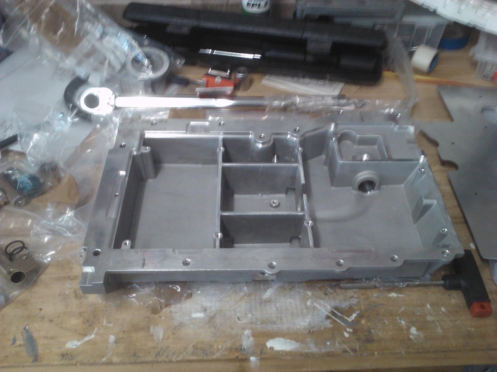
I received a package from Raceline in the UK, which had my new low profile wet sump kit and a horizontal facing oil filter housing. This allowed me to finish the motor off in preparation for attaching the clutch and gearbox and then installing the car. First job was to flip the motor over and remove the factory sump and oil filter housing. This exposed the bottom end of the engine, and as expected it was very clean given its only just over 1 year old. Next job was to remove the factory oil pickup. Once this was done, I cleaned off the existing gasket on the mating surfaces to get it ready for the new sump.

With the motor now ready, I turned to assembling the new sump. This is a relatively easy task. First you mount a block to pickup the inlet to the existing oil pump. Then you add the oil pickup pipe into the tray and connect to the oil pump pickup tray. Then you assemble the windage tray which sits above the baffles. Finally you fit a thimble gasket to the block that connects the block in the sump to the existing oil filter. From here its a dry fit, then apply the gasket and refit the new sump and torque it down. Easy job and taking your time no more than 1 hour. Last jobs were to add the sump plug, finger filter and plug and a new dipstick, before flipping the motor the right way up to marvel at my new ground clearance.
 
Lastly I fitted a new gasket and the horizontal oil filter housing low on the intake side of the block. This has an M12x1.5 threaded takeoff for the electrical oil pressure gauge. This will need an adapter as I have gone with VDO gauges, and their senders all use 1/8" 27NPT fittings. As always I have photos of every step, so if you are interested in seeing more drop me a comment.

Tuesday, February 1, 2011

Loose Ends

Not much going on at the moment while I wait for a few critical parts to show up. I have used the idle time to tidy up a few loose ends and get ready for the flurry of activity that will occur when the parts turn up.
  • Checked all the bolted connections and added the odd washer here or there where I missed out on first pass. 
  • Used the Dremel to open up the fuel filler hole in the body and test fitted the fuel cap. 
  • Marked up the additional holes that need to be cut in the dashboard for extra warning lights.
  • Fitted the handbrake lever.
  • Fitted brake pads.
  • Setup initial camber on rear hubs and camber/toe in on front hubs in preparation for wheels going in.
I have also ordered wheels and tyres, gearbox and a new wet sump and oil filter adapter. Research continues on gauges, switch gear, lighting and clutch/flywheel combos.

Sunday, January 23, 2011

Front Suspension Finished

I received the missing front stabilizer linkages this week (along with a bunch of other new bits for the engine and gear box). I set about to finish the suspension off by fitting the stabilizer linkages. I started on the right hand side, and along with everything else on the right hand side of this chassis so far, it was to tight to fit on the lower wishbone. So I set up the left side first with no dramas, adjusting the linkage length to given clearance over the steering tie rod and away from the coil spring. Once that was fitted I went back to the right side. I decided to machine down the threaded tube that fits into the wishbone rather than trying to widen the bracket, which would of damaged the powder coat on the frame. Once I knocked about 1.5mm of the tube, everything went together nicely. From here I adjusted and tightened the block connectors on the stabilizer bar, and then tightened the retaining rings on the stabilizer bar near the mounting blocks. The bolts on the mounting blocks will be tightened later. 


I finished the day by doing a "rough" camber and toe in set up on the front end, and installing the disc pads and pad retaining bolts in the front calipers.  Front end done!

Body Loom

Still at a loose end waiting for a few more parts to turn up. Decided to see what boxes I could empty to get a few more parts on the car and tidy up the garage. The electrical body loom was an easy choice as it gets a major step out of the way. I started by putting some cable ties between the dash panel and the support frame to hold the dash part of the loom. This required a gentle application of flat screwdriver to open a gap between the dash panel and the frame which is glued together with silastic. The cardboard clamped across the dash is to protect the carbon fibre which already has at least one gouge in it (perfect place for the ADR warning sticker!).


Next I popped the lid of the fuse box cover, and removed the rear support bracket in the fuse box. I was lucky enough to acquire a loom complete with relays and fuses already mounted on a bracket. So it was a (relatively) simple task to pull the sealing grommets out that provide access into the cockpit, transmission tunnel and engine bay. I fed the engine part of the loom forward first...easy!. Next I fed the largest part of the loom into the cockpit and up behind the dash. I secured the backbone of this loom to the frame with cable ties, aligning each connector behind its respective switch, gauge or light....even easier! 

Last part was the rear loom. This is separate and connects into 2 connectors on the main loom. I started feeding the rear loom through the opening from the fuse box into the transmission tunnel. This went well until the last connector (the Hall Effect sensor for the speedo) which was to large to fit through the hole with the cables in it. So I had to pull it all back and open the hole more with the Dremel (can't build a Clubman without one!). Once it was larger the rear loom went in easy and is now sitting in the passenger side footwell. I will not finish running it to the rear until I get the engine, transmission, diff and prop shaft in to make sure it all fits snug. I will also get some heat shrink and wrap all the loose leads before I tighten everything up with cable ties. Last task here is to fabricate a second bracket to mount the fuses/relays on so I can mount it in the fuse box (leaving room for the ECUs).

Thursday, January 20, 2011

Seat Runner

Not a lot of progress build wise as I have been waiting for parts to arrive. I decided to try to do a couple of little bits and pieces that would not get in the way of other build steps. Firstly I thought I would rivet on the press studs for the tonneau cover. Only problem was my rivet gun head did not fit into the press stud so it was impossible to get the rivets to fit snugly. Drilled those attempts out and will leave it for later (either getting a different rivet gun or a mobile motor trimmer to come past.

Looking through my other bits and pieces, I decided that the driver's seat runner would be easy to fit with just 4 bolts. So after putting the first 3 in ok, the 4 one seemed to be crossed in the thread. After a few retries it felt like it was moving, so I popped on the socket to only have it go PING...the bolt head sheared off. No drama, will drill out the bolt, tidy up the hole and re tap it. All good accept I hit the same level of resistance and PING, the tap is now sheared off in the same hole %^$&!!!. From here I grabbed the Dremel and a carbide grinding wheel and started to grind out the tap. Two days later and I still have only ground half the tap out and the hole in the metal is getting bigger by the minute. Mind you I am doing all this in the floor of the car, leaning in at odd angles. Then it hits me, I can pull the entire seat frame out and fix it on the bench!!!. So 5 minutes later the seat frame is on the bench, and a further 5 minutes saw the tap ground out, the lower bolt removed and replaced, the hole in the frame fixed up and the seat runner back in the car. Amazing when you think things through how quickly they are fixed! 4 bolts, 3 days :)


Tuesday, January 4, 2011

Rear Suspension

I started with the right hand side wishbones. Having read a lot of other build diaries, I expected the act of getting the washers in between the chassis and the pivot was going to be hard. The upper wishbone wasn't to bad......but the lower was unbelievable. The whole art of getting the washers to line up with the chassis holes and the pivot was a dark art. Also getting the final washer in took a very gentle hand with a hammer, needle nose pliers and a screw driver to progressively tap the washer home. So after nearly 4 hours I had one pair of wishbones in! Decided that was enough for one day and would come back tomorrow to tackle the left side. Would you believe the left side tolerances were much better and I had both wishbones on the left mounted in under 30 minutes.


Flushed with my new found success, I moved on to the right rear damper. It took a few goes to work out the right combination of spacers and washers but I think I have the top mount sorted. Bottom mount was easy although the bolt protrusion and nut fouled the front of the upright casting. I decided to set up the camber and caster now, as this would help with the shock mount fouling the upright, and I needed to make massive changes to the ball joint adjuster on the upper wishbone to get it to fit into the upright. This brings me to an interesting point. How much thread needs to be left in the upper wishbone after you have adjusted the upper ball joint for camber? The overall thread length is 34mm, and after setting up a neutral camber (admittedly with no wheels/tires on, and no load on suspension) I have exposed 19mm of thread, leaving 15mm in the wishbone as can be seen in the photo below. This doesn't seem a lot given the importance of that contact point so I will be sure to be checking this with Birkin and on the forums at Ozclubbies.com.au.


After leveling the chassis and setting up the camber and caster correctly the issue of the damper bottom mount fouling the upright has now gone. While I was in the general area, I adjusted the hard lines for the rear brakes, and attached the flexible brake lines to the hard lines, and then ran the flexible line out to the brake caliper and attached. Again everything at this stage is only finger tight. I will probably replace the brake lines with braided lines in the future, but will use what is supplied for now. I am waiting for a few missing parts, so will leave the left upright and damper off until they arrive. I still have the handbrake pivot assembly, differential, rear stabiliser and fuel tank to fit before the rear is done.


Thursday, December 30, 2010

Front suspension and steering

 So finally after having the car for 6 weeks, I was able to start building. The first mission was the front suspension and steering rack. Having had a chance to read a lot of other build diaries and learn from their adventures, the front wishbones and dampers went in with little fuss. All the bolts and nuts are only finger tight at this stage, and these will be tightened before I drop it onto its wheels, and then torqued correctly once on the ground.


Connecting the steering column to the steering rack spline proved to be an interesting task, as it would not press fit together easily and required a fair amount of persuasion to get it mated. I ended up having to remove the entire rack and the bottom half of the steering column and assemble it on the bench. 


The bolt that finally secured it was also interesting and I suspect I will take it off and replace it in the near future. One lesson learnt from the hours of reading other builders blogs was not to tighten anything and pre fit everything first. This meant the steering rack only went in 3 times!  I must be mellowing as these sort of issues that would have had me previously throwing tools and yelling expletives now merely cause me to chuckle and walk away only to come back later and solve easily.


 One thing I have come to rely on is other builders photos and descriptions as an invaluable source of truth. I have taken far more photos than are shown here, so if for some reason you find yourself using my build as a reference, feel free to drop me a line and I will share the other photos with you. 


Once the uprights and calipers went on, it started to resemble a car (from front on anyway)!


Finding an engine

While the body was in paint I was keen to maintain progress, so I started working on sourcing an engine. The initial plan was to find a wrecked car for salvage on one of the auction sites, bring it home, strip out what I needed, and sell the rest!

Few problems. The auctions were very expensive and didn't have exactly what I was after, I didn't have the space to house another car, I didn't have the time to strip it and I din't have the first clue about what I needed or where to find it in the wrecked donor.


So using a shopping list supplied by Bryn (FigJam on Ozclubbies.com.au), I shopped around a few wreckers for late model write offs (rear first obviously). Thank goodness for P Platers!!!. FORMAZ spares at Smithfield had just received a 2009 Focus 2.0 litre with 13,000km on it that had been hit heavily from behind. The guys at FORMAZ were more more than happy to collect all the parts from my list, and crate them up for pickup for me. This saved a huge amount of time and embarrassment from not knowing what a charcoal canister looked like!. End result was an engine at home after 3 days of shopping, mounted on the stand waiting to be stripped. Two nights later it was stripped and cleaned and ready for some new go faster bits!


A bit of colour

I was keen to get the main part of the tub (the chassis, scuttle, nose cone and bonnet) off to paint and back before Christmas so I could start working on the build over the Christmas holidays. The prep and painting was to be done by Josh from Kirrawee Prestige Smash Repairs. This was an important step as the body had suffered some pretty bad gouges from the shipping frame (ex factory) and the nose cone had a large gouge on one of the edges that had exposed fibres.


My youngest son was in charge of colour selection, and we came up with an Audi Orange (as seen on the A3). The guys at Kirrawee Prestige Smash Repairs did a stellar job on the repairs (you can't see them!) and the paint is gorgeous. Throughout prep and paint Josh sent me photos of the mask up, the etch primer, the colour coats and the final clear coat while it was being baked. It will be complemented by gloss black fenders and accessories, as well as black wheels and brake calipers further along in the build. We picked it up Christmas eve (hell of a pressie!) and bought it home to recommence building.

Cutting "THE HOLE"

The Birkin does not come with a hole cut in the body for the extractors. Once you decide on your engine package, this then dictates which side and where the hole must be cut to accommodate the extractors. As I am going for a Duratec motor, the hole is on the right hand side. Brenton from Meridian Motorsports kindly provided a cardboard template for the required hole.


I had read a lot of horror stories about cutting this particular hole, and I was more than a little concerned about undertaking cutting a hole in my new baby. Three days of false starts, and I settled on a 1mm Flexovit metal cutting wheel for the grinder. I cut a test line in the middle of the hole, and once I realised how easy it was, I roughed out the entire hole in about 5 minutes. That was the easy part!. I then tackled the remainder of the hole with a file to bring the cut back to the marked up line, and I then finished it up with a grinding/polishing wheel in the Dremel (which took 2 more nights to finish!). All in all not a bad result for something I was petrified of attempting.


Deconstruction

As the Birkin comes with many of the major parts already fitted (bonnet, nose cone, scuttle, fuel tank) I set about stripping these parts out in order to get the main parts to the painter before Christmas. 


Delivery Day


Mid November, Brenton from Meridian tells me that the car has shipped, and TNT will have it available for pickup on Monday morning. This calls for a day of annual leave! 


I race out to the depot to pick it up, only to be faced with a guy who didn't want me to have it. After arguing with him for 10 minutes, and then watching them use it as a forklift battering ram, I got it loaded on to the car trailer and home. 


We took our time unpacking all the boxes and then offloaded the chassis into the garage.  This allowed for the initial unveiling of the chassis as we removed the steel frame to see what we had gotten ourselves in for!


The Selection Process

Please bear with me while I catch up on this blog. This saga begins in late October 2010, but I only started the diary just after Christmas 2010.
Once I had the sign off to undertake the build, the first step was to work out what I would build. A quick scan of Ozclubbies.com.au, and a several nights of browsing sites kept bringing me back to the Birkin site. The Birkin is often compared with the Caterham, and whilst it's at the upper end price wise of Clubman kits, I am a big believer in the premise that you usually get what you pay for.
So after several emails back and forward to Brenton at Meridian Motorsports in Melbourne, and an intro to Bryn, the NSW Distributor, the order is placed and the deposit is sent. I will be the proud owner of a Birkin S3 IRS chassis!
The Birkin gives me a multitude of engine options, a relatively large knowledge bank based on the cars already sold and being built, and it is largely all new parts and bespoke components custom made by Birkin rather than a mish mash of donor parts from various outdated cars.